QINGgameplay developer

Architectural drawings to 3D handoff

Ridge House

A two-storey house drawn as a full set, then handed over the way a 3D team needs it: one coordinated model behind every sheet, schedules, a coordination log, and a build spec for Unreal Engine 5.

What this is. A self-initiated study I made to show how I read an architectural drawing set and translate it for 3D artists. It is not a client project and the building is not real.

01 · Model

The drawings, built

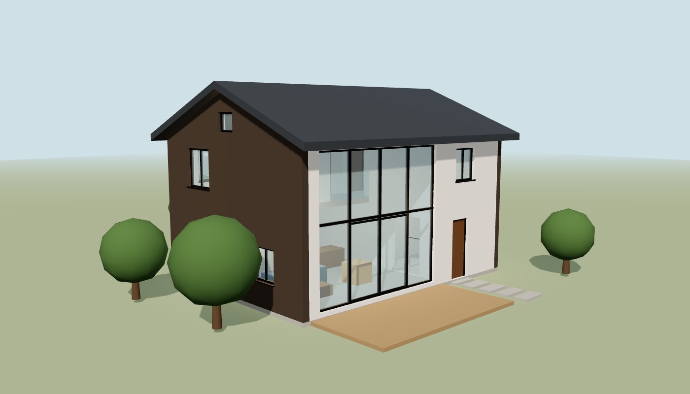
Every wall, opening, slab, stair and roof plane in this model is generated from the same data as the sheets below. Click a window or door to see its mark, size and the sheets it appears on.

Ridge House 3D model, south-west view

02 · Drawings

The drawing set

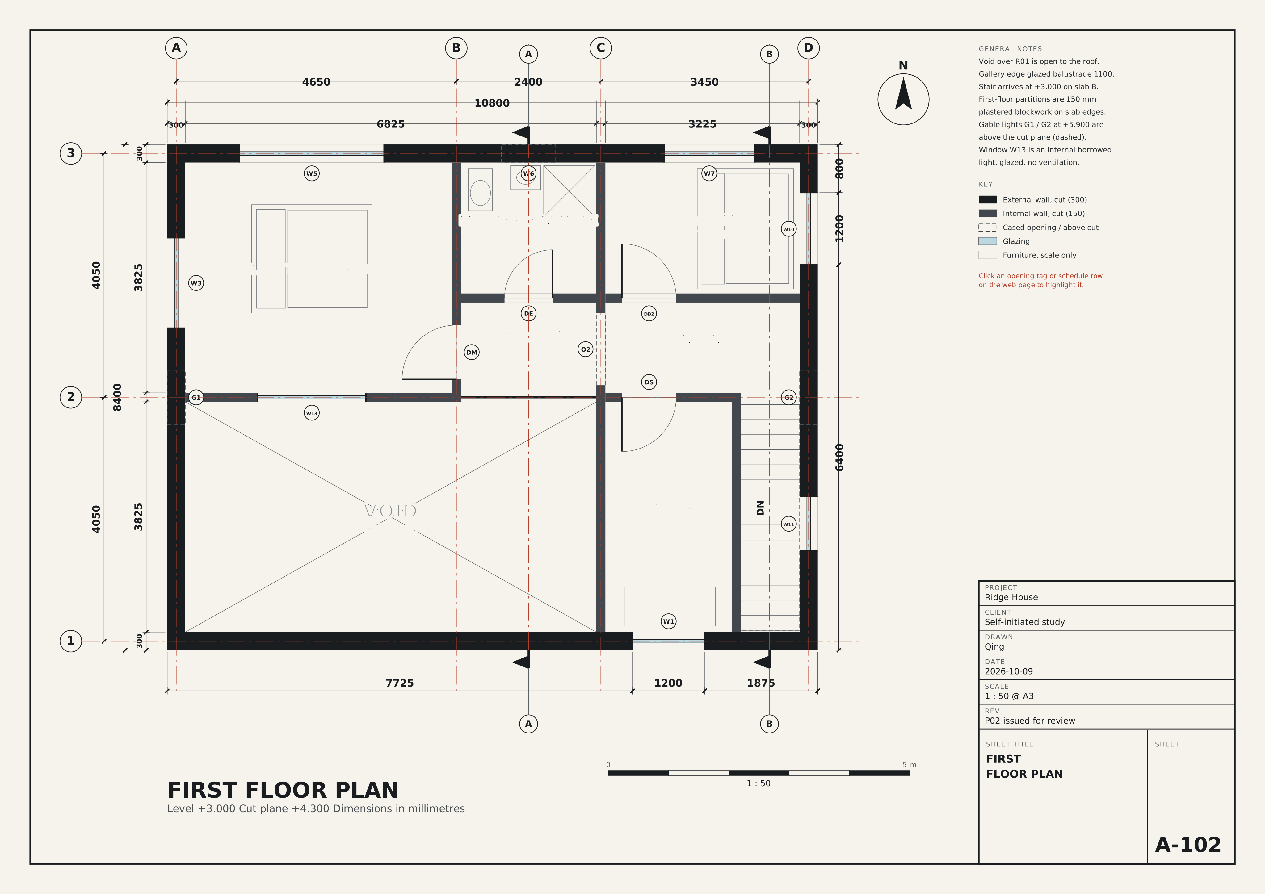
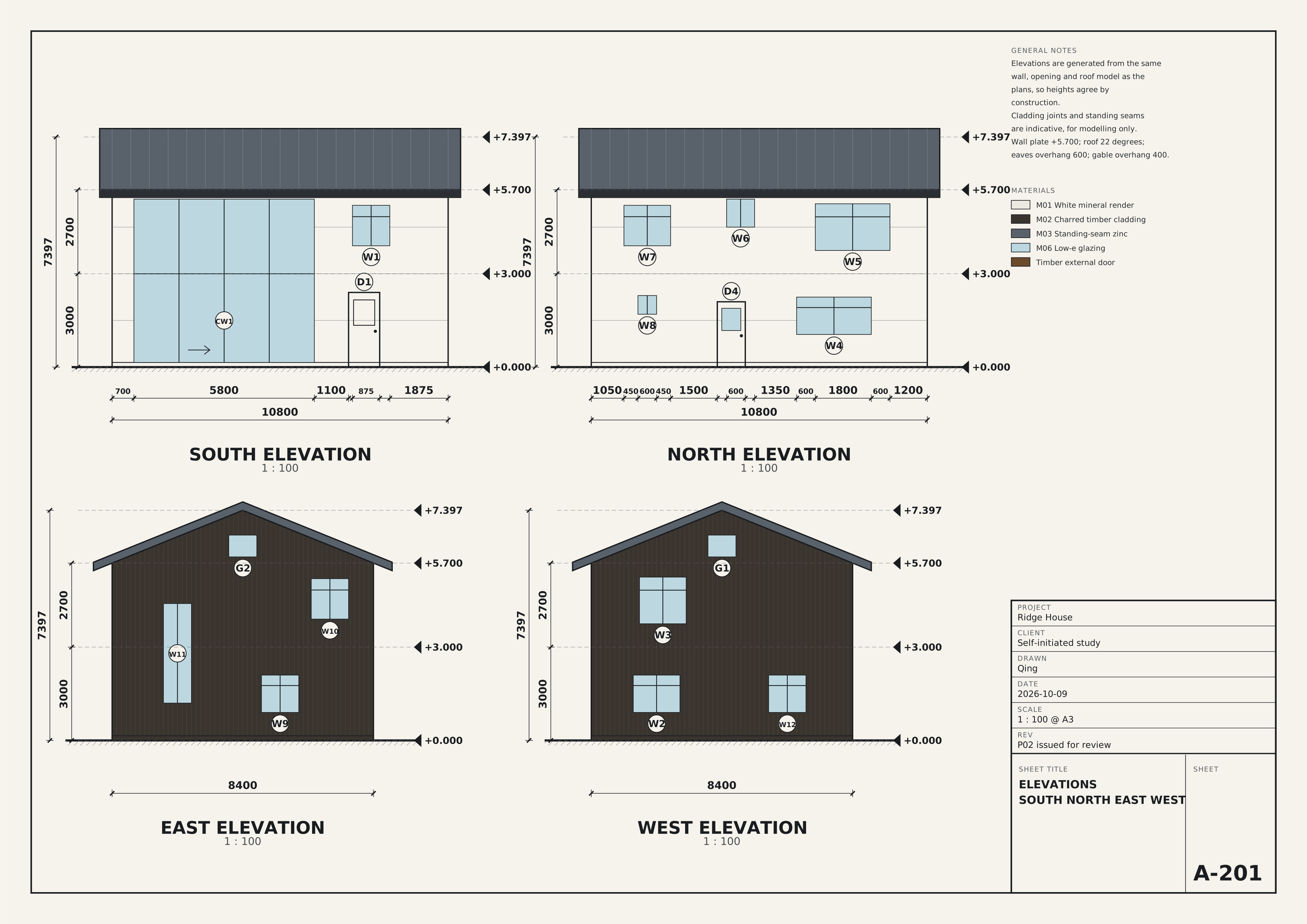
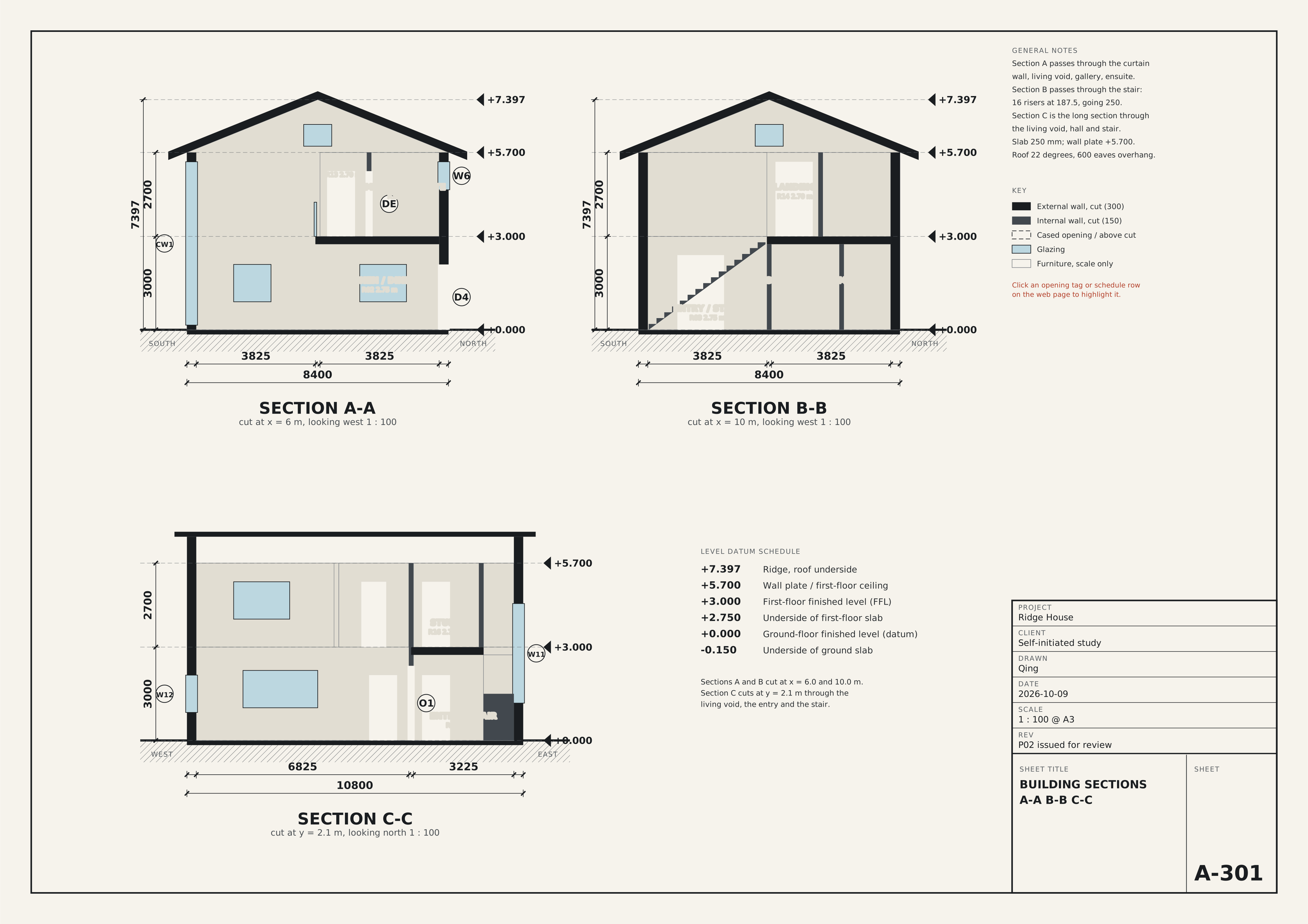
Four A3 sheets at 1:50 and 1:100, drawn the way a contractor expects to receive them. Opening tags are live: hover or click one and the schedule and the 3D model follow.

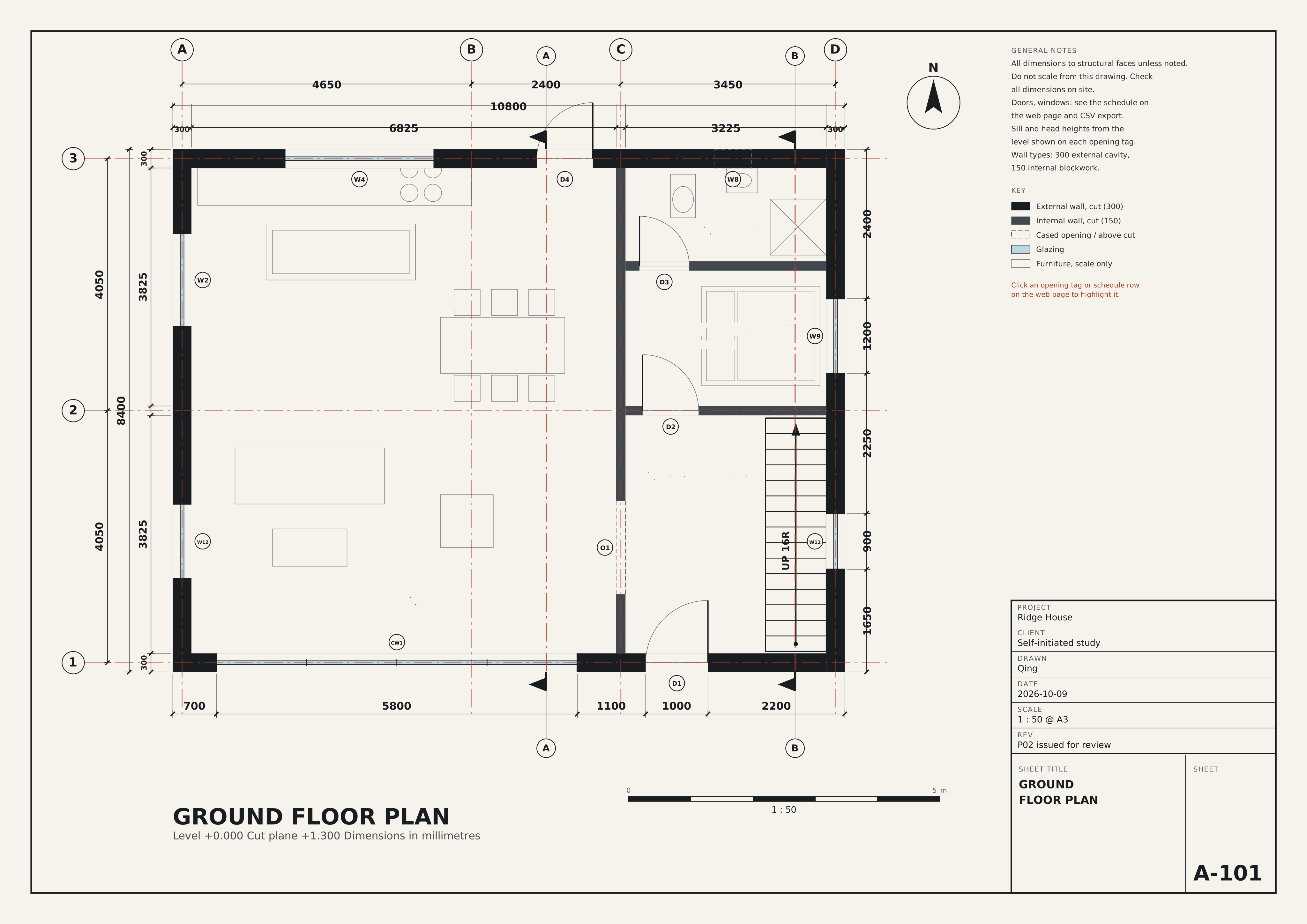
Cut at +1.300. Walls, openings with swing, stair, furniture for scale, three dimension strings per side and gridlines A to D / 1 to 3.

SVG
UP 16RCW1D1W2W12W11W9D4W4W8O1D2D3LIVINGR01 26.1 m² double heightKITCHEN / DININGR02 26.1 m²ENTRY / STAIRR03 12.3 m²GUEST BEDROOMR04 7.0 m²ENSUITER05 4.8 m²3006825322530010800465024003450ABCD3003825382530084004050405012370058001100100022001650900225012002400AABBN05 m1 : 50GROUND FLOOR PLANLevel +0.000 Cut plane +1.300 Dimensions in millimetresPROJECTRidge HouseCLIENTSelf-initiated studyDRAWNQingDATE2026-10-09SCALE1 : 50 @ A3REVP02 issued for reviewSHEET TITLEGROUNDFLOOR PLANSHEETA-101GENERAL NOTESAll dimensions to structural faces unless noted.Do not scale from this drawing. Checkall dimensions on site.Doors, windows: see the schedule onthe web page and CSV export.Sill and head heights from thelevel shown on each opening tag.Wall types: 300 external cavity,150 internal blockwork.KEYExternal wall, cut (300)Internal wall, cut (150)Cased opening / above cutGlazingFurniture, scale onlyClick an opening tag or schedule rowon the web page to highlight it.

03 · Method

How I translate drawings for a 3D team

The same five habits whether the set is a house or a hotel lobby.

  1. 01

    Fix the datum before drawing anything

    Gridlines A to D and 1 to 3, level +0.000 at ground-floor finish, roof pitch 22 degrees, wall plate +5.700, ridge +7.397. Units and origin are agreed first so every later number means one thing.

  2. 02

    Follow each opening across the whole set

    A mark such as W11 has to agree on the plan, the elevation, the section and the schedule. Click any tag on a sheet, a row in the schedule or the opening in the 3D model and the other three light up.

  3. 03

    Close the dimension chains

    Room faces plus wall thicknesses must add up to the overall length: 300 + 6825 + 150 + 3225 + 300 = 10800. When a chain does not close it becomes a question for the architect, not a guess.

  4. 04

    Write assumptions down as RFIs

    Where the drawings are silent I record what I assumed and what it changes for the 3D team, so nobody builds on an unstated decision.

  5. 05

    Hand over in engine terms

    Opening families, wall pieces, materials and a DataTable of coordinates in Unreal units, with north and handedness converted once and documented.

04 · Schedules

Opening schedule

26 openings, each with a mark, size, sill, head, room, the sheets that show it and the Unreal mesh it maps to. Sizes are structural openings in millimetres.

MarkTypeLevelWallW × HSillHeadRoomSheetsUE5 mesh
CW1Curtain wallGFExt S5800 × 52501505.40R01A-101, A-201, A-301SM_CurtainWall_580x525
D1DoorGFExt S1000 × 240002.40R03A-101, A-201SM_Door_100x240
W1WindowFFExt S1200 × 13009005.20R16A-102, A-201SM_Win_120x130
W2WindowGFExt W1500 × 12009002.10R02A-101, A-201SM_Win_150x120
W12WindowGFExt W1200 × 12009002.10R01A-101, A-201, A-301SM_Win_120x120
W3WindowFFExt W1500 × 15007505.25R11A-102, A-201SM_Win_150x150
G1Gable lightFFExt W900 × 700+5.906.60R01A-102, A-201SM_GableLight_90x70
G2Gable lightFFExt E900 × 700+5.906.60R03A-102, A-201SM_GableLight_90x70
W11WindowGFExt E900 × 3200+1.204.40R03A-101, A-102, A-201, A-301SM_Win_90x320
W9WindowGFExt E1200 × 12009002.10R04A-101, A-201SM_Win_120x120
W10WindowFFExt E1200 × 13009005.20R15A-102, A-201SM_Win_120x130
D4DoorGFExt N900 × 210002.10R02A-101, A-201, A-301SM_Door_90x210
W4WindowGFExt N2400 × 120010502.25R02A-101, A-201SM_Win_240x120
W8WindowGFExt N600 × 60017002.30R05A-101, A-201SM_Win_60x60
W5WindowFFExt N2400 × 15007505.25R11A-102, A-201SM_Win_240x150
W6WindowFFExt N900 × 90015005.40R12A-102, A-201, A-301SM_Win_90x90
W7WindowFFExt N1500 × 13009005.20R15A-102, A-201SM_Win_150x130
O1Cased openingGFInt V11500 × 240002.40R03A-101, A-301SM_Opening_150x240
O2Cased openingFFInt V11200 × 240005.40R13A-102SM_Opening_120x240
D2DoorGFInt H0a900 × 210002.10R04A-101SM_Door_90x210
DSDoorFFInt H0a900 × 210005.10R16A-102SM_Door_90x210
D3DoorGFInt H1800 × 210002.10R05A-101SM_Door_80x210
DMDoorFFInt M1900 × 210005.10R11A-102SM_Door_90x210
DEDoorFFInt E1800 × 210005.10R12A-102, A-301SM_Door_80x210
DB2DoorFFInt H2900 × 210005.10R15A-102SM_Door_90x210
W13WindowFFInt H0w1800 × 12009005.10R11A-102SM_Win_180x120

Rooms

IDRoomLvlArea m²Height mGlazing / floor
R01LivingGF26.15.40125%
R02Kitchen / DiningGF26.12.7518%
R03Entry / StairGF12.32.7528%
R04Guest BedroomGF7.02.7521%
R05EnsuiteGF4.82.757%
R11Master BedroomFF16.92.7035%
R12Master EnsuiteFF4.92.7017%
R13GalleryFF3.42.70–
R14LandingFF4.82.70–
R15Bedroom 2FF7.02.7050%
R16StudyFF8.02.7019%
Net internal area121.5

Quantities

External faceGross m²Openings m²Net m²Glazed
South58.134.423.759%
North58.111.546.620%
East55.06.548.512%
West55.06.148.911%
Total226.358.5167.826%
  • Footprint90.7 m²
  • Roof area, two planes120.1 m²
  • First-floor slab, 250 mm49.4 m² · 12.4 m³
  • Internal wall length31.9 m

05 · Coordination

Checks run on the set

These run against the model every time the sheets are generated. 21 pass, 4 are notes for the architect, 0 fail.

StatusRuleResultSheet
PassPlan chain along X closes to overall width300 + 6825 + 150 + 3225 + 300 = 10800 (overall 10800)A-101
PassPlan chain along Y closes to overall depth300 + 3825 + 150 + 3825 + 300 = 8400 (overall 8400)A-101
NoteFirst-floor partitions stacking on ground-floor walls1 of 5 stack directly; the rest sit on the 250 slabA-102
PassStair 2R + G between 550 and 700R 187.5 / G 250: 2R+G = 625A-301
PassStair rise 16 x R equals floor-to-floor16 x 187.5 = 3000A-301
PassStair top nosing clears hall north wallTop tread ends at y = 4080; wall face at 4125A-101
PassStair clear width at least 800975 mm between wall face and wall faceA-101
PassDoors have at least 800 mm structural opening8 doors, narrowest 800Schedule
PassDoor heads at least 2100All doors 2100 or higherSchedule
PassEvery opening sits inside its wall extent with at least 100 mm return26 openings checkedSchedule
PassNo two openings overlap in the same wallNo overlapsSchedule
PassDoor swings clear of fixed furniture and stairArcs of D2, D3, DB2, DE, DM and DS tested against the layoutA-101 / A-102
PassR01 Living: glazing at least 10% of floor area32.52 m2 / 26.1 m2 = 125% (CW1 + W12 + G1)Schedule
PassR02 Kitchen / Dining: glazing at least 10% of floor area4.68 m2 / 26.1 m2 = 18% (W2 + W4)Schedule
PassR03 Entry / Stair: glazing at least 10% of floor area3.51 m2 / 12.3 m2 = 28% (G2 + W11)Schedule
PassR04 Guest Bedroom: glazing at least 10% of floor area1.44 m2 / 7.0 m2 = 21% (W9)Schedule
PassR05 Ensuite: glazing at least 5% of floor area0.36 m2 / 4.8 m2 = 7% (W8)Schedule
PassR11 Master Bedroom: glazing at least 10% of floor area5.85 m2 / 16.9 m2 = 35% (W3 + W5)Schedule
PassR12 Master Ensuite: glazing at least 5% of floor area0.81 m2 / 4.9 m2 = 17% (W6)Schedule
NoteR13 Gallery: no direct glazingLit from the living void and curtain wall CW1A-201
NoteR14 Landing: no direct glazingLit by stair slot W11 across the open stairA-201
PassR15 Bedroom 2: glazing at least 10% of floor area3.51 m2 / 7.0 m2 = 50% (W10 + W7)Schedule
PassR16 Study: glazing at least 10% of floor area1.56 m2 / 8.0 m2 = 19% (W1)Schedule
PassRoof plane passes through the wall top at both eavesz(y=0) = 5700; ridge 7397 at y = 4200 for 22 degreesA-301
NoteCurtain wall head leaves a structural band to the roof plateHead z = 5400; wall top 5700; band 300 mmA-301

Assumptions and questions for the architect

RFI-01A-301

Curtain wall CW1 leaves only 300 mm between its head and the wall plate at +5.700. Is a steel header or the eaves beam inside that band, and what is the finished soffit height?

Assumed: Assumed a 300 mm structural beam hidden in the band; head fixed at +5.400.

Effect on 3D: High: affects the CW1 module height and the roof support in 3D.

RFI-02A-101

Wall INT-V1 between living and hall is drawn full height. Is it masonry or stud? The 3D team needs the thickness at the O1 reveal.

Assumed: Assumed 150 mm plastered blockwork carrying the first-floor slab edge.

Effect on 3D: Medium: changes the opening reveal and collision thickness.

RFI-03A-102

Gallery edge at gridline 2 shows a balustrade symbol but no height or type. Glass or timber, and is 1100 mm the intended height?

Assumed: Assumed frameless glass, 1100 mm, fixed to the slab edge.

Effect on 3D: Low: one asset, but it controls sightlines from the gallery into the double-height room.

RFI-04A-201

Gable lights G1 and G2 are shown on the elevation but not on any plan, because the plan cut is below them. Confirm they are fixed rectangular panes and not circular.

Assumed: Assumed 900 x 700 rectangular fixed glazing with 200 mm reveals.

Effect on 3D: Low: two small assets, but they are visible from the double-height room.

RFI-05A-101

Landing R14 has no direct window. Is borrowed light from the stair slot W11 acceptable, or should a rooflight be added?

Assumed: Assumed borrowed light through the open stair void is acceptable.

Effect on 3D: Medium: a rooflight would add a new opening in the roof and change the lighting set-up.

RFI-06A-301

Roof overhang is dimensioned at the eaves (600) but not at the gables. Section shows about 400. Confirm.

Assumed: Assumed 400 mm gable overhang with a fascia of 270 mm.

Effect on 3D: Low: roof mesh extents.

06 · Unreal Engine 5

Handoff spec for the 3D team

This is the specification I would give the artists and the level designer. It is a document and a data set, not an Unreal project.

Coordinates and units

  • Drawing unitsmillimetres
  • Unreal units1 UU = 1 cm, so divide by 10
  • Originouter south-west corner of the ground slab, at +0.000
  • Axesdrawing east = +X · drawing north = −Y · up = +Z
  • Why −YUnreal is left-handed, so with +X east, +Y points south
  • Snapevery opening edge falls on a 25 mm grid
  • Opening locationcentre of the opening, in the wall plane
  • Door/window yaw0° on east-west walls, 90° on north-south walls

Naming

  • Static meshSM_Win_150x120, SM_Door_90x210
  • MaterialM_Render_White, M_Zinc_Roof
  • BlueprintBP_RidgeHouse, BP_Door_Hinged
  • Mesh keywidth × height in cm, one mesh per unique size
  • Pivotbottom-left of the opening, on the wall centreline
  • Collisionsimple box per wall piece, glass blocks, frames do not

Opening families

18 unique meshes cover 26 openings. Click a mark to find it in the model.

MeshTypeW × H mmCountMarks
SM_CurtainWall_580x525Curtain wall5800 × 52501
SM_Door_100x240Door1000 × 24001
SM_Door_80x210Door800 × 21002
SM_Door_90x210Door900 × 21005
SM_GableLight_90x70Gable light900 × 7002
SM_Opening_120x240Cased opening1200 × 24001
SM_Opening_150x240Cased opening1500 × 24001
SM_Win_120x120Window1200 × 12002
SM_Win_120x130Window1200 × 13002
SM_Win_150x120Window1500 × 12001
SM_Win_150x130Window1500 × 13001
SM_Win_150x150Window1500 × 15001
SM_Win_180x120Window1800 × 12001
SM_Win_240x120Window2400 × 12001
SM_Win_240x150Window2400 × 15001
SM_Win_60x60Window600 × 6001
SM_Win_90x320Window900 × 32001
SM_Win_90x90Window900 × 9001

Wall pieces

Walls are cut into solid pieces at every opening column, which gives 33 wall meshes for the whole building.

WallType, mmLength mHeight mOpening columnsSolid pieces
EXT-SExternal 30010.205.7023
EXT-NExternal 30010.205.7034
EXT-WExternal 3008.405.7034
EXT-EExternal 3008.405.7045
INT-V1Internal 1507.805.7023
INT-H0aInternal 1502.255.7012
INT-H0bInternal 1500.972.7501
INT-H1Internal 1503.232.7512
INT-M1Internal 1503.832.7012
INT-H0wInternal 1504.582.7012
INT-E1Internal 1502.252.7012
INT-H2Internal 1503.232.7012
INT-S1Internal 1503.832.7001

Materials

IDMaterialUsed onUnreal asset
M01White mineral renderSouth and north external wallsM_Render_White
M02Vertical charred-timber claddingEast and west gable wallsM_Timber_Charred
M03Standing-seam zincRoof, 22 degree pitchM_Zinc_Roof
M04Polished concreteGround slab, upper slab, floorsM_Concrete_Polished
M05Plaster, matt warm whiteInternal partitions and soffitsM_Plaster_Warm
M06Low-e double glazingAll glazingM_Glass_LowE
M07Dark bronze aluminiumWindow, door and curtain-wall framesM_Alu_Bronze
M08Oak deckingFront terraceM_Oak_Deck
M09Oak treads on concrete stringerMain stairM_Oak_Stair

Notes for the build

  • Build order. Slabs and wall pieces first, then roof, then the opening meshes from the DataTable, then the curtain wall which depends on RFI-01.
  • Double-height space. Living R01 is open to the roof, so lighting and reflection captures need to be set up for a 5.4 m volume with a glass wall to the south.
  • Stair. 16 risers at 187.5 mm, 15 treads at 250 mm, 975 mm clear. Build it as one mesh with the gameplay-facing collision as a ramp if characters will use it.
  • Interior walls. 150 mm partitions on the first floor sit on the slab edge, not on a wall below. They are separate meshes so they can move without touching the structure.
  • Scale references. The furniture in the model is for scale only and is not part of the architectural scope.

07 · Files

Download the package

The same files a 3D team would receive.

Want to see how I would run a real set?

I am happy to walk through this package on a call, including the questions I would raise with the architect and how I would agree the first week of the 3D build.